Introduction
A variable DC power supply is one of the most important tools for an electronics hobbyist. In order to carry out an experiment you need a reliable DC power source that can be varied according to the need of the experiment. Last week I felt I must have one on my workbench, and thought to make one for myself. This design is very simple but is great for powering almost all kinds electronic projects. It uses LM350 (a 3-pin IC) to generate a variable DC power supply. I would recommend to read the datasheet before doing this project.
The LM350 is an adjustable 3-terminal positive voltage regulator that is capable of supplying in excess of 3A over a 1.2V to 33V output range. They are exceptionally easy to use and require only 2 external resistors to set the output voltage.

Main Features
Requirements
You need following things to make this variable power supplies.
Circuit Diagram
First of all you need to generate an unregulated 24V DC using the step-down transformer and the rectifier circuit. Use the 1000uF capacitor at the output to reduce the ripples. The circuit is shown below.

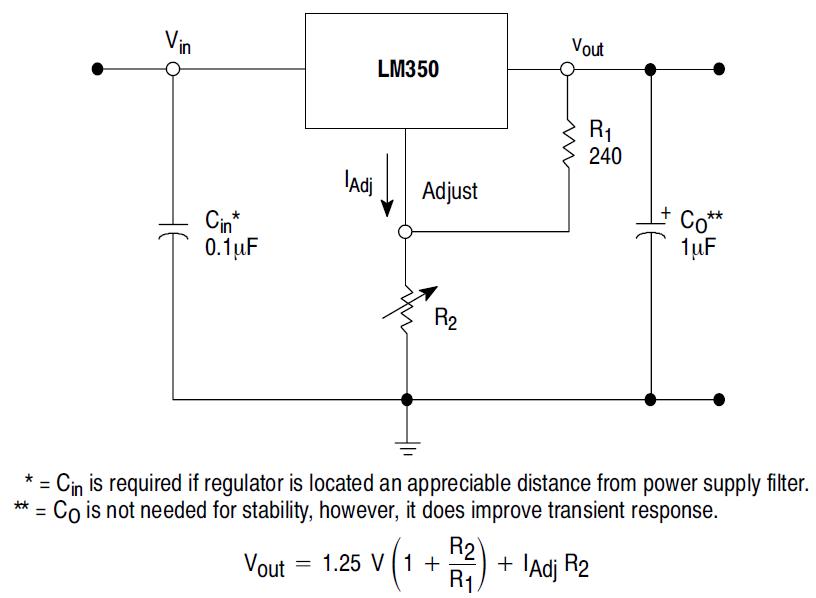
Next comes LM350 IC that takes in this unregulated 24V DC and with the use of two resistors (R1 = 360 Ohm, R2 = 5K Potentiometer) you can derive variable DC voltage. The circuit diagram along with the equation for output voltage is shown below. I took this circuit from LM350 datasheet and it shows R1 = 240 Ohm, but I am gonna use 360 Ohm as I am generating 18V DC at maximum.

The value of IAdj is about 100uA, so the error term is almost negligible.
Other things that are not included in the circuits above are a power on LED and the analog voltmeter display. I connected the LED to the output unregulated 24V DC through 4.7K resistor. This indicates the power switch is ON. Also connect the voltmeter to final output voltage terminals to display what voltage is being generated. Remember the heat sink for LM350.
Assembly
Here are some of the pictures that I took while making this power supply.


I hope this project will be helpful to you and you have enjoyed reading this.
A variable DC power supply is one of the most important tools for an electronics hobbyist. In order to carry out an experiment you need a reliable DC power source that can be varied according to the need of the experiment. Last week I felt I must have one on my workbench, and thought to make one for myself. This design is very simple but is great for powering almost all kinds electronic projects. It uses LM350 (a 3-pin IC) to generate a variable DC power supply. I would recommend to read the datasheet before doing this project.
The LM350 is an adjustable 3-terminal positive voltage regulator that is capable of supplying in excess of 3A over a 1.2V to 33V output range. They are exceptionally easy to use and require only 2 external resistors to set the output voltage.

Main Features
- Adjustable output down to 1.2V
- Guaranteed 3A output current
- Guaranteed thermal regulation
- Output is short circuit protected
Requirements
You need following things to make this variable power supplies.
- A 120/24V transformer
- A bridge rectifier IC or four general purpose diodes.
- Capacitors: 1000 uF, 50 V electrolyte (1), 0.1 uF ceramic (1), 1 uF, 50 V electrolyte (1)
- Resistors: 360 Ohm (1), 5 K potentiometer (1), 4.7K (1)
- A Rocker Switch for AC ON/OFF
- A voltmeter display (I used an analog one)
- An LED for power on indication.
- A heat sink for LM350
- Wires, prototyping board, soldering iron, box, etc as per required.
Circuit Diagram
First of all you need to generate an unregulated 24V DC using the step-down transformer and the rectifier circuit. Use the 1000uF capacitor at the output to reduce the ripples. The circuit is shown below.

Fig. Bridge Rectifier Circuit using 4 Diodes
Other things that are not included in the circuits above are a power on LED and the analog voltmeter display. I connected the LED to the output unregulated 24V DC through 4.7K resistor. This indicates the power switch is ON. Also connect the voltmeter to final output voltage terminals to display what voltage is being generated. Remember the heat sink for LM350.
Assembly
Here are some of the pictures that I took while making this power supply.


Finalized product.
I hope this project will be helpful to you and you have enjoyed reading this.
Hey nice and tidy project.
ReplyDeletethanx
kp up da gd wrk
Thank you Sakvith!
ReplyDeleteThanks
ReplyDeleteThis project is really needed to me.
Hello Raj,
ReplyDeleteif you want to start the voltage from 0vcc, you have to add 2 diodes (which both must support 3 amps, because for opening a diode, 0,6v is required ), in series, at the output of the LM 350.
its really nice .............
ReplyDeleteThanks Ducu for your suggestion.
ReplyDeletehello this is interesting project!
ReplyDeletei just wanna ask if there is a chance of increasing the 3A to 5A ?...
Thanks..=)
Read the datasheet for LM350 (http://www.national.com/mpf/LM/LM350.html#Overview). They have some application circuits for higher o/p current.
ReplyDeletehi i m kanfa from jakarta indonesia i m interested on your website i need your
ReplyDeletehelp to make schematics of power supply 70-550 Volt and frequency 1 kHz- 20 kHz
for design work coil diameter 10" and height 15" for melting 25 kg metal
capacity and I ll compensite /donate on your job thanks best regards