Introduction
This project describes how to program PIC16F628A to function as a 00-99 min programmable timer. User can set any time between 00-99 minutes and can turn ON a device for that period. The device will be automatically turned OFF after the time expires. For demonstration, the ON/OFF condition of device is simulated by switching LED ON and OFF. With the use of three input switches (unit, ten, start/stop) the user can set ON time of the timer and can also control Start/Stop operation. The two time set switches are for selecting unit and tens digit of minute time interval (00-99). Once you set the value of minute interval, pressing the Start/Stop will turn the timer ON (LED will glow), and pressing the same button again at any point of time during timer operation will interrupt the process (LED will turn OFF) and the timer will be reset. LCD display will provide timer status and user interface for setting time.
Setup
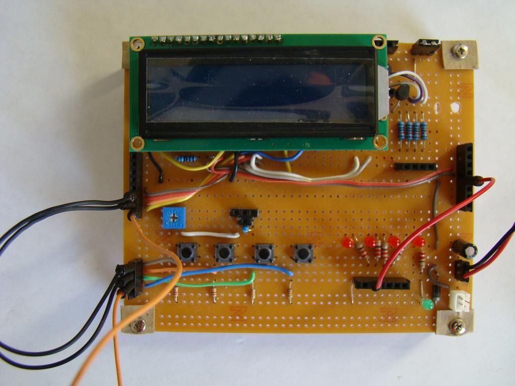
Connect SW1, SW2, and SW3 to RB0, RB1, and RB2 respectively. SW1 will serve Start/Stop, SW2 as unit minute, and SW3 as tens minute. Connect a LED to RA3 port.


Software
/*
############################################
Project: 00-99 Minutes Timer
Designed By: Rajendra Bhatt
Date: Sep 03, 2010
############################################
LCD Data D4-D7 connected to RB4-RB7
LCD RS -> RA0
LCD E -> RA1
Start/Stop Time Select -> RB3
Unit Min Switch -> RB0
Tens Min Switch -> RB1
Cancel Switch -> RB2
Relay -> RA3
*/
// LCD module connections
sbit LCD_RS at RA0_bit;
sbit LCD_EN at RA1_bit;
sbit LCD_D4 at RB4_bit;
sbit LCD_D5 at RB5_bit;
sbit LCD_D6 at RB6_bit;
sbit LCD_D7 at RB7_bit;
sbit LCD_RS_Direction at TRISA0_bit;
sbit LCD_EN_Direction at TRISA1_bit;
sbit LCD_D4_Direction at TRISB4_bit;
sbit LCD_D5_Direction at TRISB5_bit;
sbit LCD_D6_Direction at TRISB6_bit;
sbit LCD_D7_Direction at TRISB7_bit;
// End LCD module connections
// Tact switches and Relay ports
sbit Relay at RA3_bit;
sbit SS_Select at RB0_bit; // Start Stop Time Select
sbit Unit_Button at RB1_bit;
sbit Ten_Button at RB2_bit;
// Messages
char Message1[]="00-99 min Timer";
char Message2[]="Device ON";
char Message3[]="Device OFF";
char Message4[]="Set Time: min";
char Message5[]="Time Left: min";
unsigned short i, j, unit=0, ten=0, ON_OFF=0, index=0, clear, time;
char *digit = "00";
// 300ms Delay
void Delay_300(){
Delay_ms(300);
}
void Display_Digits(){
digit[1]=unit+48;
digit[0]=ten+48;
Lcd_Out(2,11,digit);
}
void start_timer(unsigned short tmin){
unsigned short temp1, temp2;
Relay = 1;
ON_OFF = 1;
Lcd_Cmd(_LCD_CLEAR);
Lcd_Out(1,1,Message2);
Lcd_Out(2,1,Message5);
OPTION_REG = 0x80 ;
INTCON = 0x90;
for (i=0; i< tmin; i++){
temp1 = (tmin-i)%10 ;
temp2 = (tmin-i)/10 ;
Lcd_Chr(2, 12, temp2+48);
Lcd_Chr(2, 13, temp1+48);
j=1;
do {
Delay_ms(1000);
j++;
} while(((j<=60) && (Clear ==0)));
if (Clear) {
Relay = 0;
Delay_ms(500);
Lcd_Out(1,1,Message3);
INTCON = 0x00;
goto stop;
}
}
stop: Relay = 0;
ON_OFF = 0;
unit = 0;
ten = 0;
clear = 1;
}
void interrupt(void){
if (INTCON.INTF == 1) // Check if INTF flag is set
{
Clear = 1;
INTCON.INTF = 0; // Clear interrupt flag before exiting ISR
}
}
void main() {
CMCON |= 7; // Disable Comparators
TRISB = 0b00001111;
TRISA = 0b11110000;
Relay = 0;
Lcd_Init(); // Initialize LCD
start:
clear = 0;
Lcd_Cmd(_LCD_CLEAR); // Clear display
Lcd_Cmd(_LCD_CURSOR_OFF); // Cursor off
Lcd_Out(1,1,Message1);
Lcd_Out(2,1,Message4);
Display_Digits() ;
do {
if(!Unit_Button){
Delay_300();
unit ++;
if(unit==10) unit=0;
Display_Digits();
} // If !Unit_Button
if(!Ten_Button){
Delay_300();
ten ++;
if(ten==10) ten=0;
Display_Digits();
} // If !Ten_Button
if(!SS_Select){
Delay_300();
time = ten*10+unit ;
if(time > 0) start_timer(time);
} // If !SS_Select
if(clear){
goto start;
}
} while(1);
}
Output
When the power is first turned on, you will see this on LCD screen.

Use SW2 and SW3 to chose time between 00-99 min.

When you press SW1 (Start/Stop), the LED connected at RA3 will be turned ON and you will see the time left message on the screen too.

When the time is UP, or you press SW1 again, the timer will be interrupted, LED will turn OFF, and the timer is reset to original condition.
This project describes how to program PIC16F628A to function as a 00-99 min programmable timer. User can set any time between 00-99 minutes and can turn ON a device for that period. The device will be automatically turned OFF after the time expires. For demonstration, the ON/OFF condition of device is simulated by switching LED ON and OFF. With the use of three input switches (unit, ten, start/stop) the user can set ON time of the timer and can also control Start/Stop operation. The two time set switches are for selecting unit and tens digit of minute time interval (00-99). Once you set the value of minute interval, pressing the Start/Stop will turn the timer ON (LED will glow), and pressing the same button again at any point of time during timer operation will interrupt the process (LED will turn OFF) and the timer will be reset. LCD display will provide timer status and user interface for setting time.
Setup
Connect SW1, SW2, and SW3 to RB0, RB1, and RB2 respectively. SW1 will serve Start/Stop, SW2 as unit minute, and SW3 as tens minute. Connect a LED to RA3 port.

Software
/*
############################################
Project: 00-99 Minutes Timer
Designed By: Rajendra Bhatt
Date: Sep 03, 2010
############################################
LCD Data D4-D7 connected to RB4-RB7
LCD RS -> RA0
LCD E -> RA1
Start/Stop Time Select -> RB3
Unit Min Switch -> RB0
Tens Min Switch -> RB1
Cancel Switch -> RB2
Relay -> RA3
*/
// LCD module connections
sbit LCD_RS at RA0_bit;
sbit LCD_EN at RA1_bit;
sbit LCD_D4 at RB4_bit;
sbit LCD_D5 at RB5_bit;
sbit LCD_D6 at RB6_bit;
sbit LCD_D7 at RB7_bit;
sbit LCD_RS_Direction at TRISA0_bit;
sbit LCD_EN_Direction at TRISA1_bit;
sbit LCD_D4_Direction at TRISB4_bit;
sbit LCD_D5_Direction at TRISB5_bit;
sbit LCD_D6_Direction at TRISB6_bit;
sbit LCD_D7_Direction at TRISB7_bit;
// End LCD module connections
// Tact switches and Relay ports
sbit Relay at RA3_bit;
sbit SS_Select at RB0_bit; // Start Stop Time Select
sbit Unit_Button at RB1_bit;
sbit Ten_Button at RB2_bit;
// Messages
char Message1[]="00-99 min Timer";
char Message2[]="Device ON";
char Message3[]="Device OFF";
char Message4[]="Set Time: min";
char Message5[]="Time Left: min";
unsigned short i, j, unit=0, ten=0, ON_OFF=0, index=0, clear, time;
char *digit = "00";
// 300ms Delay
void Delay_300(){
Delay_ms(300);
}
void Display_Digits(){
digit[1]=unit+48;
digit[0]=ten+48;
Lcd_Out(2,11,digit);
}
void start_timer(unsigned short tmin){
unsigned short temp1, temp2;
Relay = 1;
ON_OFF = 1;
Lcd_Cmd(_LCD_CLEAR);
Lcd_Out(1,1,Message2);
Lcd_Out(2,1,Message5);
OPTION_REG = 0x80 ;
INTCON = 0x90;
for (i=0; i< tmin; i++){
temp1 = (tmin-i)%10 ;
temp2 = (tmin-i)/10 ;
Lcd_Chr(2, 12, temp2+48);
Lcd_Chr(2, 13, temp1+48);
j=1;
do {
Delay_ms(1000);
j++;
} while(((j<=60) && (Clear ==0)));
if (Clear) {
Relay = 0;
Delay_ms(500);
Lcd_Out(1,1,Message3);
INTCON = 0x00;
goto stop;
}
}
stop: Relay = 0;
ON_OFF = 0;
unit = 0;
ten = 0;
clear = 1;
}
void interrupt(void){
if (INTCON.INTF == 1) // Check if INTF flag is set
{
Clear = 1;
INTCON.INTF = 0; // Clear interrupt flag before exiting ISR
}
}
void main() {
CMCON |= 7; // Disable Comparators
TRISB = 0b00001111;
TRISA = 0b11110000;
Relay = 0;
Lcd_Init(); // Initialize LCD
start:
clear = 0;
Lcd_Cmd(_LCD_CLEAR); // Clear display
Lcd_Cmd(_LCD_CURSOR_OFF); // Cursor off
Lcd_Out(1,1,Message1);
Lcd_Out(2,1,Message4);
Display_Digits() ;
do {
if(!Unit_Button){
Delay_300();
unit ++;
if(unit==10) unit=0;
Display_Digits();
} // If !Unit_Button
if(!Ten_Button){
Delay_300();
ten ++;
if(ten==10) ten=0;
Display_Digits();
} // If !Ten_Button
if(!SS_Select){
Delay_300();
time = ten*10+unit ;
if(time > 0) start_timer(time);
} // If !SS_Select
if(clear){
goto start;
}
} while(1);
}
Output
When the power is first turned on, you will see this on LCD screen.

Use SW2 and SW3 to chose time between 00-99 min.

When you press SW1 (Start/Stop), the LED connected at RA3 will be turned ON and you will see the time left message on the screen too.

When the time is UP, or you press SW1 again, the timer will be interrupted, LED will turn OFF, and the timer is reset to original condition.
hi,
ReplyDeletecan you upload .HEX file ?
regards
dimitri
I can't upload files on blogspot.com. I can send u in email if you want?
ReplyDeletehello
Deleteplease send me hexacode file
jimmymkadange48@gmail.com
Hello
ReplyDeletePlease send me hexcode by email
preda_panapan@yahoo.co.th
regards
preda
thailand
Thank you for your great example,
ReplyDeleteI have modified the code and added extra function
please see
http://www.digitalbirth.co.uk/blog/item/0-99-count-down-timer
Please send me hexcode by email
ReplyDeletelukovac.djordje@gmail.com
regards
Great work
ReplyDeleteall components available here in India at www.onlinetps.com
Hello
ReplyDeletePlease send me hexcode by email
norikatzu@hotmail.com
Regards
Norikatzu
Japan
I would appreciate a copy of your hex code.
ReplyDeletePlease e-mail to 38brunel@gmail.com
Thanks
Hi,
ReplyDeletePlease send me hexcode by email
gblioju@gmail.com
Thanks
Gheorghe
Romania
It worked well. I just copy and paste it. I had same setup on portb same as urs, but used 20Mhz osc.
ReplyDeleteThose 3 btns connected to portb with 10k resistors. The OPTION_REG = $80 meant it is disable. But 3 btns connected to portb w/out resistors. Meant it is enable. Am I right?
ReplyDeleteIt was my mistake, it is not required here as I already have external pull-up resistors. You can find my more advanced Timer project here:
ReplyDeletehttp://embedded-lab.com/blog/?p=1378
Hi
ReplyDeletePlease send me hexcode by email
andrespvz@gmail.com
Thanks
Andres
Chile
hi,
ReplyDeletecan you send me the .HEX file ?
at nikos_samos@yahoo.gr
Nikos...
Hello,
ReplyDeletecan you send me hex file?
koko_g@abv.bg
Thanks in advanced,
Nikolay
Hi Raj-
ReplyDeleteThanks for a great intro for embedded ckts. Could you please send the hex file : dntoorkey@gmail.com
Thanks and regards
stylianoupanayiotis1@hotmail.com
ReplyDeleteCould you please send the hex file
hi, I would appreciate if you send me the hex file
ReplyDeletexolo10.sm@gmail.com
amigo tem o lay
ReplyDeletegreat project. can i add buzzer in this project.
ReplyDeleteplease reply with solution