
About DS1820
I suggest reading my previous articles on DS1820 for getting details about this 1-wire temperature sensor. The firmware that I wrote works only for DS1820 (it may work for DS18S20 making some change in the temperature conversion time, read http://www.maxim-ic.com/datasheet/index.mvp/id/3021). It will definitely not work for DS18B20.
DS1820 converts temperature in to a 9-bit digital word, which is read by PIC16F688 as two bytes (TempH and TempL). The value of the least significant bit is 0.5°C. For positive temperature, the next eight bits after the LSB gives the integer part of the temperature. For example, 000110011 represents 25.5°C. Further, the floating-point math can be avoided during C to F conversion by using a scale factor of 10. Therefore, 25.5°C (scaled 255) is converted to F as,
TempinF = 9*TempinC/5 + 320 = 9*255/5 +320 = 779 (which is 76.9 F)
However, the negative temperatures are stored in 2's complement form. So the most significant bit of the 2-byte temperature reading from DS1820 is 1 if the temperature is below 0°C. The firmware takes care of all negative temperature readings (in both C and F scales). The computed temperature is displayed on LCD as a 5-digit string array, xxx.x (e.g., 24.5, 101.0, -12.5, etc).
Circuit Diagram
The circuit diagram of this project is shown below. DS1820 sensor output is read by PIC16F688 through RA5 port. The computed temperature is converted to a string and sent to the LCD to display. The LCD is operating in 4-bit mode, and ports RC0-RC3 serves D4-D7 data pins of the LCD. The Register Select (RS) and Enable (E) signals for LCD are provided through ports RC4 and RC5. The Read/Write pin of the LCD is permanently grounded, as there is no data read from the LCD in this project. The contrast adjustment of LCD is done with the 10K potentiometer shown in the circuit diagram.


Besides, there are two tact switches in the design. The first one serves as the system reset that is to reset the whole system and reinitialize the LCD. The another tact switch is connected to the external interrupt pin of PIC16F688. This is the toggle switch for the LCD back light. This is helpful in reading the temperature display in low illumination conditions. An interrupt service routine is written for back light toggling. When the system is first turned ON, the LCD back light turns ON by default.
The following circuit can be used to get +5V regulated power supply required for the circuit.

Firmware
The firmware was developed with mikroC compiler from mikroelektronika. The in-built library routines for DS1820 make the firmware development easier. The code is provided with adequate comments so that the reader won't have much difficulty in understanding programming logic.
/*
Digital Room Thermometer using PIC16F688
Copyright@Rajendra Bhatt
July 13, 2010
*/
// LCD module connections
sbit LCD_RS at RC4_bit;
sbit LCD_EN at RC5_bit;
sbit LCD_D4 at RC0_bit;
sbit LCD_D5 at RC1_bit;
sbit LCD_D6 at RC2_bit;
sbit LCD_D7 at RC3_bit;
sbit LCD_RS_Direction at TRISC4_bit;
sbit LCD_EN_Direction at TRISC5_bit;
sbit LCD_D4_Direction at TRISC0_bit;
sbit LCD_D5_Direction at TRISC1_bit;
sbit LCD_D6_Direction at TRISC2_bit;
sbit LCD_D7_Direction at TRISC3_bit;
// End LCD module connections
// Back Light Switch connected to RA1
sbit BackLight at RA1_bit;
// Define Messages
char message0[] = "LCD Initialized";
char message1[] = "Room Temperature";
// String array to store temperature value to display
char *tempC = "000.0";
char *tempF = "000.0";
// Variables to store temperature register values
unsigned int temp_whole, temp_fraction, temp_value;
signed int tempinF, tempinC;
unsigned short C_Neg=0, F_Neg=0, TempH, TempL;
void Display_Temperature() {
// convert Temp to characters
if (!C_Neg) {
if (tempinC/1000)
// 48 is the decimal character code value for displaying 0 on LCD
tempC[0] = tempinC/1000 + 48;
else tempC[0] = ' ';
}
tempC[1] = (tempinC/100)%10 + 48; // Extract tens digit
tempC[2] = (tempinC/10)%10 + 48; // Extract ones digit
// convert temp_fraction to characters
tempC[4] = tempinC%10 + 48; // Extract tens digit
// print temperature on LCD
Lcd_Out(2, 1, tempC);
if (!F_Neg) {
if (tempinF/1000)
tempF[0] = tempinF/1000 + 48;
else tempF[0] = ' ';
}
tempF[1] = (tempinF/100)%10 + 48; // Extract tens digit
tempF[2] = (tempinF/10)%10 + 48;
tempF[4] = tempinF%10 + 48;
// print temperature on LCD
Lcd_Out(2, 10, tempF);
}
// ISR for LCD Backlight
void interrupt(void){
if (INTCON.INTF == 1) // Check if INTF flag is set
{
BackLight =~BackLight; // Toggle Backlight
Delay_ms(300) ;
INTCON.INTF = 0; // Clear interrupt flag before exiting ISR
}
}
void main() {
TRISC = 0x00 ;
TRISA = 0b00001100; // RA2, RA3 Inputs, Rest O/P's
ANSEL = 0b00000000;
PORTA = 0b00000000; // Start with Everything Low
PORTC = 0b00000000; // Start with Everything Low
CMCON0 = 0b00000111;
Lcd_Init(); // Initialize LCD
Lcd_Cmd(_LCD_CLEAR); // CLEAR display
Lcd_Cmd(_LCD_CURSOR_OFF); // Cursor off
BackLight = 1;
Lcd_Out(1,1,message0);
Delay_ms(1000);
Lcd_Out(1,1,message1); // Write message1 in 1st row
// Print degree character
Lcd_Chr(2,6,223);
Lcd_Chr(2,15,223);
// different LCD displays have different char code for degree
// if you see greek alpha letter try typing 178 instead of 223
Lcd_Chr(2,7,'C');
Lcd_Chr(2,16,'F');
// Interrupt Setup
OPTION_REG = 0x00; // Clear INTEDG, External Interrupt on falling edge
INTCON.INTF = 0; // Clear interrupt flag prior to enable
INTCON.INTE = 1; // enable INT interrupt
INTCON.GIE = 1; // enable Global interrupts
do {
//--- perform temperature reading
Ow_Reset(&PORTA, 5); // Onewire reset signal
Ow_Write(&PORTA, 5, 0xCC); // Issue command SKIP_ROM
Ow_Write(&PORTA, 5, 0x44); // Issue command CONVERT_T
INTCON.GIE = 1; // 1-wire library disables interrpts
Delay_ms(600);
Ow_Reset(&PORTA, 5);
Ow_Write(&PORTA, 5, 0xCC); // Issue command SKIP_ROM
Ow_Write(&PORTA, 5, 0xBE); // Issue command READ_SCRATCHPAD
// Read Byte 0 from Scratchpad
TempL = Ow_Read(&PORTA, 5);
// Then read Byte 1 from Scratchpad
TempH = Ow_Read(&PORTA, 5);
temp_value = (TempH << 8)+ TempL ;
// check if temperature is negative
if (temp_value & 0x8000) {
C_Neg = 1;
tempC[0] = '-';
// Negative temp values are stored in 2's complement form
temp_value = ~temp_value + 1;
}
else C_Neg = 0;
// Get temp_whole by dividing by 2
temp_whole = temp_value >> 1 ;
if (temp_value & 0x0001){ // LSB is 0.5C
temp_fraction = 5;
}
else temp_fraction = 0;
tempinC = temp_whole*10+temp_fraction;
if(C_Neg) {
tempinF = 320-9*tempinC/5;
if (tempinF < 0) {
F_Neg = 1;
tempF[0] = '-';
tempinF = abs(tempinF);
}
else F_Neg = 0;
}
else tempinF = 9*tempinC/5 + 320;
//--- Format and display result on Lcd
Display_Temperature();
} while(1);
}
Snapshots of temperature measurements
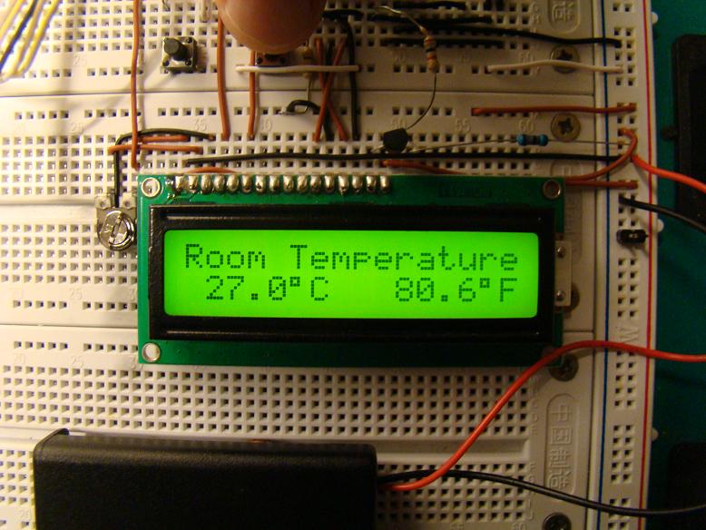
Back Light ON

Back Light OFF

Freezer Temperature

Soldering Iron Temperature
85 is the default temperature reading of DS1820 when it is first powered up.
ReplyDeletehello
ReplyDeletewhy after i program it to pic it just display in zero degrees and 32 Fahrenheit
Hi, if you want to solve this problem, you must to add the following line "WPUA = 0;", in the main function.
DeleteSir, please give me the whole simulation files for this project on my email.
ReplyDeletef50_nka@yahoo.com
regards,
Nuwa
can you tell me where i add this WPUA = 0; in the program
ReplyDeletehello sir. may i ask, can we use PIC 16F877A for this project? because we've tried and it didn't work...we dunno what is the problem.
ReplyDeleteI have not found ds 1820..
ReplyDeleteCan any one tell me? In which store it can be available in ahmedabad or nadiad or vadodara?
Plz reply..
Hello,
ReplyDeletegreat project! I have a couple of questions:
1.Can I use PIC16f628A for this project (recompile the source code for this PIC16f628A)? Are there some modification need to be made?
2.The DS1820 is nearly impossible to find in my country,can I substitute it with some other temp sensor like lm35 or so?
Thank you
Can you translate to hex file, please ?
ReplyDeletecan you please give me the full details of the project?
ReplyDeletesir kindly i need ur help i m unable to run ur code i have no configs and even it is not running kindly provide me hex file of this file plzz and also i tried ur code of seven segment that is not running too plz tell me why
ReplyDeletethanks
I also get 0.00 and 32
ReplyDeleteDid u use 16F628A?
Deletesir , i need ur help..pls provide me code and hex @shreenivass1990@gmail.com..thank you so much
ReplyDeletesir, i would like to test the circuit, may you send the hex file for me?
ReplyDeletethanks
jimmyghost21@gmail.com
I have used 16F628A. everythings working.But at the start its shows 0c and 32 F? how can i correct it?
ReplyDeleteHello duminda
Deletei am feeling interested to build this
can u please help me for it
thank you
sir , i need ur help..pls provide me code and hex veersakr@gmail.com ..thank you so much
ReplyDeleteSir, please give me the whole simulation files for this project on my email.
ReplyDeletenirob2090@gmail.com
regards,
Nirob
if i want to connect a relay to be drived at a specific temperature what should be the changes in code, please.
ReplyDeleteranatauseef2002@gmail.com