Introduction
The Timer0 module in PIC16F628A is both 8-bit Timer and Counter. When used as Counter, the Timer0 module will increment on every rising or falling edge of the T0CKI (RA4, pin 3) pin. The incrementing edge is determined by the T0SE bit of the OPTION register.


Counter mode is selected by setting the T0CS bit to 1 in the OPTION register. You can see from the above table that the minimum prescaler is 1:2 for TMR0. In order to get 1:1 prescaler for Timer0, the prescaler must be assigned to the WDT module. So for our purpose, the value of OPTION register could be 0b00101000 (28h). Now, the Timer0 will work as an 8-bit counter, counting the pulses arrived at RA4/T0CKI pin at low-to-high transition.
Setup
In this experiment we are going to measure the mains AC frequency by using Timer0 as counter. The mains AC frequency is 120V, so we cannot directly feed it to PIC port. We need to first step down the 120V AC first to appropriate level. I am going to use a 12V transformer for this purpose. The 12V AC sine wave output from the transformer will be further converted to 5V square waves (approximately) using a BJT switch. I built this additional circuit on a breadboard. The 5V square waves will be fed to T0CKI port of PIC16F628A. The number of pulses arrived at port T0CKI within 1 second will be the frequency of the input signal.
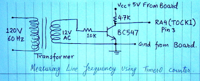
 Note: Don't forget to connect the emitter ground to the ground of PIC16F628A development board.
Now connect the collector of BC547 transistor to T0CKI port (pin 3). Put the 16x2 character LCD module on its socket on the board.
Software
/*
Project Name: Use of Timer 0 as counter
* Copyright: (c) Rajendra Bhatt, 2010.
* Description: Timer0 counter reads mains frequency and
display on LCD
* Test configuration:
MCU: PIC16F628A
Oscillator: XT, 4.0 MHz
*/
// LCD module connections
sbit LCD_RS at RA0_bit;
sbit LCD_EN at RA1_bit;
sbit LCD_D4 at RB4_bit;
sbit LCD_D5 at RB5_bit;
sbit LCD_D6 at RB6_bit;
sbit LCD_D7 at RB7_bit;
sbit LCD_RS_Direction at TRISA0_bit;
sbit LCD_EN_Direction at TRISA1_bit;
sbit LCD_D4_Direction at TRISB4_bit;
sbit LCD_D5_Direction at TRISB5_bit;
sbit LCD_D6_Direction at TRISB6_bit;
sbit LCD_D7_Direction at TRISB7_bit;
// End LCD module connections
// Define Messages
char message1[] = "Frequency= Hz";
char *freq = "000";
void Display_Freq(unsigned int freq2write) {
freq[0] = (freq2write/100) + 48; // Extract hundreds digit
freq[1] = (freq2write/10)%10 + 48; // Extract tens digit
freq[2] = freq2write%10 + 48; // Extract ones digit
// print temperature on LCD
Lcd_Out(1, 11, freq);
}
void main() {
CMCON |= 7; // Disable Comparators
TRISB = 0b00000000; // set direction to be output
Lcd_Init();
Lcd_Cmd(_LCD_CLEAR); // Clear display
Lcd_Cmd(_LCD_CURSOR_OFF); // Cursor off
Lcd_Out(1,1,message1); // Write message1 in 1st row
OPTION_REG = 0b00101000; // TOCS=1 for Counter mode, PSA=1 for 1:1 prescaler
do {
TMR0=0;
Delay_ms(1000); // Delay 1 Sec
Display_Freq(TMR0);
} while(1); // Till PORTB < 15
}
Output
You will see the mains AC frequency displayed on the LCD.

The Timer0 module in PIC16F628A is both 8-bit Timer and Counter. When used as Counter, the Timer0 module will increment on every rising or falling edge of the T0CKI (RA4, pin 3) pin. The incrementing edge is determined by the T0SE bit of the OPTION register.


Setup
In this experiment we are going to measure the mains AC frequency by using Timer0 as counter. The mains AC frequency is 120V, so we cannot directly feed it to PIC port. We need to first step down the 120V AC first to appropriate level. I am going to use a 12V transformer for this purpose. The 12V AC sine wave output from the transformer will be further converted to 5V square waves (approximately) using a BJT switch. I built this additional circuit on a breadboard. The 5V square waves will be fed to T0CKI port of PIC16F628A. The number of pulses arrived at port T0CKI within 1 second will be the frequency of the input signal.


Now connect the collector of BC547 transistor to T0CKI port (pin 3). Put the 16x2 character LCD module on its socket on the board.
Software
/*
Project Name: Use of Timer 0 as counter
* Copyright: (c) Rajendra Bhatt, 2010.
* Description: Timer0 counter reads mains frequency and
display on LCD
* Test configuration:
MCU: PIC16F628A
Oscillator: XT, 4.0 MHz
*/
// LCD module connections
sbit LCD_RS at RA0_bit;
sbit LCD_EN at RA1_bit;
sbit LCD_D4 at RB4_bit;
sbit LCD_D5 at RB5_bit;
sbit LCD_D6 at RB6_bit;
sbit LCD_D7 at RB7_bit;
sbit LCD_RS_Direction at TRISA0_bit;
sbit LCD_EN_Direction at TRISA1_bit;
sbit LCD_D4_Direction at TRISB4_bit;
sbit LCD_D5_Direction at TRISB5_bit;
sbit LCD_D6_Direction at TRISB6_bit;
sbit LCD_D7_Direction at TRISB7_bit;
// End LCD module connections
// Define Messages
char message1[] = "Frequency= Hz";
char *freq = "000";
void Display_Freq(unsigned int freq2write) {
freq[0] = (freq2write/100) + 48; // Extract hundreds digit
freq[1] = (freq2write/10)%10 + 48; // Extract tens digit
freq[2] = freq2write%10 + 48; // Extract ones digit
// print temperature on LCD
Lcd_Out(1, 11, freq);
}
void main() {
CMCON |= 7; // Disable Comparators
TRISB = 0b00000000; // set direction to be output
Lcd_Init();
Lcd_Cmd(_LCD_CLEAR); // Clear display
Lcd_Cmd(_LCD_CURSOR_OFF); // Cursor off
Lcd_Out(1,1,message1); // Write message1 in 1st row
OPTION_REG = 0b00101000; // TOCS=1 for Counter mode, PSA=1 for 1:1 prescaler
do {
TMR0=0;
Delay_ms(1000); // Delay 1 Sec
Display_Freq(TMR0);
} while(1); // Till PORTB < 15
}
Output
You will see the mains AC frequency displayed on the LCD.

Hi Raj. I am very new with PIC programming. I am still unable to decide which IDE to use. Can you help with what is easy compiler to start with.
ReplyDeleteThanks,
Kaushlesh
IF you are new, if you know C, I would suggest to use mikroC. It is easy to use and it has large in-built library routines. The free version allows you to compile codes up to 2K, which is enough for beginners. All the projects I have posted on this blog use the free version of mikroC.
ReplyDeleteI am using pic16F628A. On PORTB connected resistors to 7-segment
ReplyDeleteLet say IF I want to enable PORTB pull-ups and set the prescalar to 1:32.
That means i can set "OPTION_REG = $04"?
Or could be "OPTION_REG = $84"?
Which one could i used option_reg?
regards,
supra
You don't need to enable internal pull-ups to drive a seven segment display. Internal pull-ups are required when the port pins are used as inputs.
ReplyDeletehello, thank you for your online work, just a little mistake i noticed:
ReplyDeleteit's not:
freq[1] = (freq2write/100) + 48; // Extract hundreds digit
but
freq[0] = (freq2write/100) + 48; // Extract hundreds digit
cheers
Thanks for pointing out that. I corrected it.
ReplyDeletehi,
ReplyDeleteyour work is nice. i need a program for 50Hz output frequency generator for driving a triac board.iam using microc compiler only.
is it possible to measure frequency from DCLOCK (in ISIS Proteus 7 simulation) ?
ReplyDeletei want to make digital ac voltmeter using pic 16f628a kindly help me
ReplyDelete