
Programmable digital timer with a relay switch

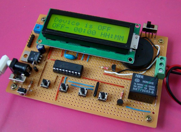
This project shows how to make a simple programmable digital timer switch with a PIC16F628A microcontroller. The timing schedule for the relay switch can be programmed through 4 push buttons. The program menu, the status of the relay switch and time information is shown on a character LCD.


The circuit details and firmware are available to download at www.embedded-lab.com in the Projects section.

Comments

Popular posts from this blog

Contact less tachometer using PIC16F628A

Introduction Tachometer is a device that gives you the information about the rotational speed of any shaft or disc. It usually measures the speed in revolutions per minute (RPM). Today we are going to make a simple tachometer that could measure the rotation speed of a disk without making any physical contact (that's why it is contact less) with the rotating object. The range of this tachometer is 0 - 9999 RPM and displays the RPM on a multiplexed 4-digit seven-segment display. Of course, we are going to do this project on our usual PIC16F628A development board. Infrared sensor Contact-less measurement of RPM will be achieved through an IR sensor. An IR diode will send a beam of infrared towards the rotating disc, and any reflected pulse will be received by a photo diode. The resistance of a photo diode drops drastically when exposed to infrared. An infrared is reflected by a white surface and absorbed by the dark ones. The test disc for this project is shown below. You can see ...

PIC16F628A Development Board

The development board we are going to make for our experimental microcontroller PIC16F628A will look like this. Here are the features it is going to have: Access to all I/O pins through female header pins 4 Push Buttons for Input 4 LEDs for Output An LCD Interface Port A 4-digit Seven-Segment Display Interface LCD Backlight Switch and Contrast Adjustment ICSP Programming (Very Important)

Experiment No. 3: LCD Interface in 4-bit Mode

The objective of this experiment is to interface a 16x2 LCD to PIC16F628A in 4-bit mode. This means the data transfer will use only four pins of the microcontroller. There is no additional hardware setup needed for this experiment, as we have a ready-made LCD interface female header. We only need to define the data transfer and control pins in the software. Remember, the LCD interface in our development board uses the following pins of PIC16F628A: Data Transfer : D4 -> RB4, D5 -> RB5, D6 -> RB6, D7 -> RB7 RS -> RA0, and EN -> RA1