
PIC based Diode and BJT tester

If your digital multimeter does not have features for testing diodes and transistors, hold on, here's a project that describes how you can construct one by yourself. This project is based on a PIC16F688 microcontroller and uses the simple concept of unidirectional conduction of PN juction to find if the diode or transistor is good or bad. The test results are displayed on a character LCD. It also shows the type of the transistor (NPN or PNP) as well as which of the PN junctions are open or short in a faulty transistor.

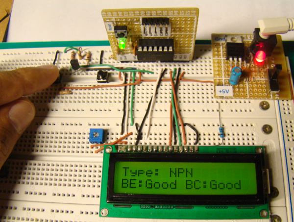
Source: http://embedded-lab.com/blog/


The firmware is developed using MikroC Pro for PIC compiler. For the details of the circuit diagram and firmware, visit here

Comments

Popular posts from this blog

Experiment No. 3: LCD Interface in 4-bit Mode

The objective of this experiment is to interface a 16x2 LCD to PIC16F628A in 4-bit mode. This means the data transfer will use only four pins of the microcontroller. There is no additional hardware setup needed for this experiment, as we have a ready-made LCD interface female header. We only need to define the data transfer and control pins in the software. Remember, the LCD interface in our development board uses the following pins of PIC16F628A: Data Transfer : D4 -> RB4, D5 -> RB5, D6 -> RB6, D7 -> RB7 RS -> RA0, and EN -> RA1

Contact less tachometer using PIC16F628A

Introduction Tachometer is a device that gives you the information about the rotational speed of any shaft or disc. It usually measures the speed in revolutions per minute (RPM). Today we are going to make a simple tachometer that could measure the rotation speed of a disk without making any physical contact (that's why it is contact less) with the rotating object. The range of this tachometer is 0 - 9999 RPM and displays the RPM on a multiplexed 4-digit seven-segment display. Of course, we are going to do this project on our usual PIC16F628A development board. Infrared sensor Contact-less measurement of RPM will be achieved through an IR sensor. An IR diode will send a beam of infrared towards the rotating disc, and any reflected pulse will be received by a photo diode. The resistance of a photo diode drops drastically when exposed to infrared. An infrared is reflected by a white surface and absorbed by the dark ones. The test disc for this project is shown below. You can see ...

Experiment No. 5: Multiplexed Seven Segment Displays

In this experiment, we are going to learn how to interface more than one 7-segment LED display to a PIC Port using multiplexing technique. We are going to interface a 4-digit common cathode seven segment display to our PIC board. The multiplexing circuit is already built up in the board using 4 transistors and few resistors (Read Make Your Own PIC Development Board ). The basic idea of multiplexing is that all seven segment displays are connected to the microcontroller in parallel and the microcontroller alternately prints ones, tens, hundreds, and thousands digits, selecting one at a time. The switching among the digits is so fast that it gives an impression of simultaneous light emission. Experimental Setup: 1. Connect RA0 through RA3 to 7-Segment Digit Select headers DG1, DG2, DG3, and DG4 using jumper wires. 2. Insert 7FR5641AS 4-Digit Seven Segment module in to its place on the board.